Drawing Triangles on N64
When developing my Nintendo 64 game Voidblade, an important step was rendering the triangles. The basic building block of any modern 3D pipeline is a triangle, even to this day (according to Brian Karis’s latest SIGGRAPH talk, it will probably take “many years” until we start using different representations like voxels). Thus, it is generally the first step whenever you pick up a new rendering API to start learning it. Drawing a triangle, sounds easy right? Wasn’t so easy for me on this particular system and I will try to explain my high level understanding of the underlying hardware in this blog post. It took about 2 weeks for me to come up with the proper commands to feed to the rasterizer for rendering transparent triangles due to the lack of proper documentation and hardware quirks. It still has a few issues for a few edge cases (even causing random and unpredictable crashes that I still need to investigate) but works ok in general.
First for a little bit of context; on the console, there is a main MIPS CPU which generally runs the overall logic of the game and orchestrates other processors, namely the RSP (reality signal processor – a SIMD style vector processing unit) and RDP (reality display processor – a command based hardware rasterizer). Nintendo 64 was one of the systems of the time that provided a specialized hardware rasterizer, that I need to tame. Basically, the RSP reads 64bit commands from the provided buffer (which can be either on the main ram of the system (RDRAM) or provided by the RSP via XBUS) and executes them. In my implementation I have used Rasky’s RDRAM library to build a basic CPU implementation to generate rasterization commands without spending too much time on the cpu reading/writing to the display buffer. In an ideal rendering engine, RSP will constitute an important part of the process to save CPU cycles but currently libdragon - my primary choice of N64 development library - does not have a ready to use solution to build it easily until this PR is merged, so I went for a simpler CPU implementation.
The gist of rendering a basic triangle is providing the rasterizer with an X and Y start position (in fixed point). Then it starts writing to the screen buffer line by line. To decide on moving to the next line and where to start on the next line, it uses the slopes of the various edges as illustrated on this diagram at a very high level;
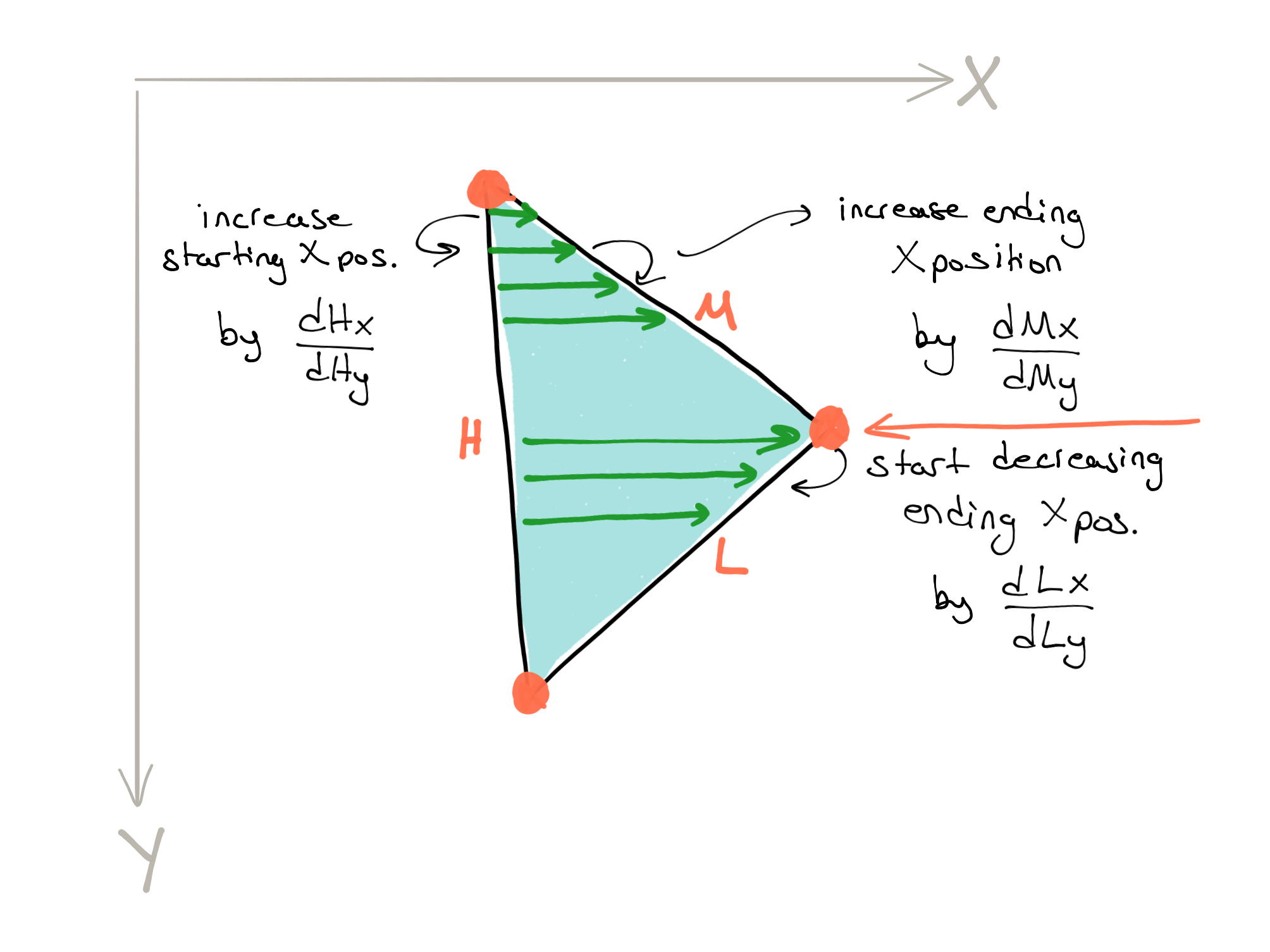
RDP starts writing pixels from the top and proceeds line by line moving to the next one when the x position reaches a threshold. Then it increases y position by one and updates the starting x position with respect to the previous start position. For the above illustration, threshold value is increased by the slope of the M edge and starting x position is increased by the slope of the H edge. Once the y position moves past the inflection point, it starts using the slope of the L edge, effectively decreasing the threshold this time (the slope is always added). In reality the things are a little bit more complicated because the actual rasterization starts from the previous pixel if the starting point is inside the pixel (there are 4 vertical subpixels). Also the deflection starts at the next subpixel so there are a few edge cases where additional adjustments are necessary. Additionally, there is another variant where the inflection point is on the left and the triangle should be rendered in a different order. For a more in depth explanation see Snacchus’s guide (also see the full source here).
Then there is the question of telling the rasterizer what to render while going through this sequence. That is primarily configured using the set other modes command. In my case I was using flat coloured triangles with transparency for which I need to enable blending and read enable bits so that RDP will read from the buffer and mix it with the primitive color that we are newly rasterizing. The whole thing executes on the RDRAM which makes the console heavily fill-rate limited. Another important thing that I should mention, and was probably the most difficult to figure out, is the seam between triangles. As a matter of the fact it is very sensitive on color combiner settings, which I used only to try it at some point but it ended up costing many hours of debugging. Once the color combiner glitch was fixed, I was configuring the coverage unit such that it properly mixes those edges.
The hardware provides a coverage unit capable of calculating a coverage value of 3 bits per pixel, which is written to the target buffer. Consider this pixel with its 8 subpixels;
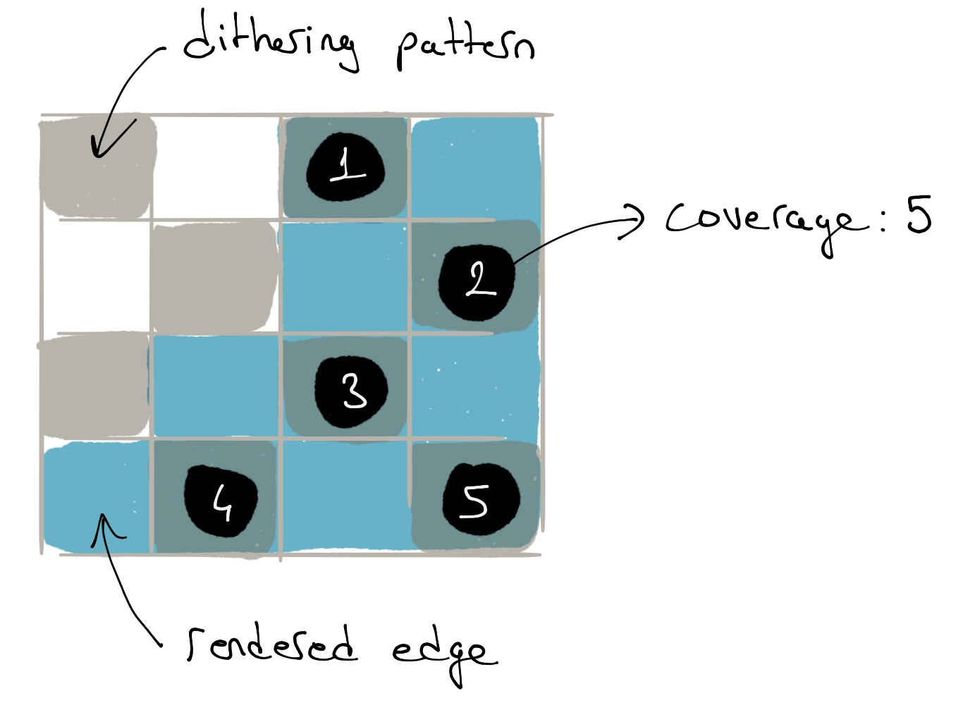
Here the blue subpixels represent where the edge is covering in the subpixel array. To save hardware cost only the half of the subpixels are used in the calculation and the above dithering mask is used to decide on which ones to keep. For this example, 5 pixels are covered. The alpha channel’s least significant 3 bits are used to store these coverage values. This means that it can create a 3-bit value for every pixel on an edge, such that it can mix colors from different primitives on these boundary pixels. The coverage value is always updated to the sum of the existing value and the one from the newly rendering primitive and starts at 0. The mix equation is;
(p x a + m x b) / (a + b)
Here, p is the new pixel’s colour, m is the colour at target buffer location and a and b are the coverage values of the new pixel and memory respectively. As an example if the coverage value is 4, when the other part of the seam is rendered on the same pixel (again with a coverage of 4, where having complementary values is a design requirement) the color from the first primitive will be written as-is increasing the target coverage to 4 causing the next primitive to get mixed in a 1:1 ratio.
On the outer edges of the primitives, this coverage value is also used to blend the pixel color with the nearby fully covered pixels in the video filter (at a later stage) and those outer edges are thus anti-aliased in the final image. Effectively, the coverage value represents the “transparency” of that edge and assuming the background color behind this edge pixel is the same as the average of its neighbours, the hardware approximates a super sampling operation. Because this process is actually averaging over pixel values in the image to decide on the final color, it is one of the reasons why N64 images are known to be blurry.
With this coverage mechanism in place, if you think about transparent primitives on a triangle seam, there is a problem in contrast to the example with solid colors above. When rendering both primitives by mixing the target color using the coverage values, we would end up mixing the transparent color with the already mixed color from the other primitive. This would result in an incorrect color, for example consider when the primitive transparency is 50% and coverage is 50% and we are rendering white on black. The first primitive writes gray at 50% brightness, being the first one to update target coverage but the second primitive will mix this color 1:1 with its 50% gray resulting in a 75% gray. In reality, the brightness should be the same on the seam as well. Instead, the hardware uses a special coverage mode where it starts with an alpha channel of all 1s in the buffer.
When the first edge pixel is rasterized, the coverage is added to the value in the buffer, initially wrapping around. Because the value wraps and there is this special color on wrap mode which only writes the pixel color if the value wraps, the pixel is mixed with the existing value and is written to the buffer forming the final color. When the other triangle on the same seam is rendered, it should now have a coverage value that can make the total all 1s again (remember the coverages are complementary) and when it is added to the existing buffer it does not wrap preventing a re-render on that pixel. The same mechanism still works if the buffer was last written a value other than all 1s due to an outer edge as only one of the two triangles sharing the seam will cause a wrap. I think this is a really good use of very limited hardware resources for a specific problem.
This was my rather high level understanding of the rasterizer hardware summarized. It primarily represents my own thought process when thinking about it, and not necessarily how the underlying hardware formally works. In the end, I haven’t actually utilized the color combiner or transparency but still left these as is in the code for future reference. I hope I can fully utilize transparent primitives in the future for a project! Hope this was an interesting introduction to the N64 hardware rendering for you! Also, it may become useful to someone working on the console as well. Do not forget to drop a comment or reach me out in case you have something to tell!