Dumping Korg i5m PCM ROMs – part 2 - Learning to Fail
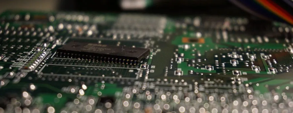
Previously I have started writing on fixing my korg i5m (part-1). Removing the ROM chips was not fixing the problem but taking advantage of this opportunity, I have started trying to dump them out. The problem was that I was not sure if I am reading correct values or not. After working for hours and fiddling with address lines using an oscilloscope, I was able to get some consistent results. Sometimes some of the address lines was getting stuck resulting in repeating patterns in the dump. To make things worse, the memory layout of samples is not very clear except for GM1, which apparently just have 8 bit signed PCM data all aligned properly. After getting an acceptable output for this particular chip, I am pretty confident now that I am doing things right but have some connection issues due to contact resistance (or maybe CMOS-TTL incompatibility as someone over hackaday has suggested). Reading the contents of every chip and being able to sometimes get the same exact data out increased my confidence on the contents of the other chips although they are not perfectly aligned PCM data as the first one - thus harder to verify. I believe the odds of getting the exact same data with inconsistent connections is pretty low though. I am also sure that I have every possible hex value in the output assuring all data bits have proper connection. Here are the statistics (from 00 to FF on x-axis) of the perfectly aligned chip and a sample PCM waveform from its contents;


(BTW audacity is a great tool foor quickly checking PCM data) Now as I have dumped the contents, it is time for looking after the actual problem again. Resoldering ROMs back into place until I get all internal tests on i5 to pass (meaning no read errors on ROM lines), I started to think about possible causes. Other candidates on my mind are DRAM and SRAM chips that are temporarily holding sample data during playback. Disabling all the DSP effects on the device makes the output silent suggesting the problem is indeed on the digital output stage. I then started randomly shorting out RAM address lines together to make them become corrupt while listening on the earphones. Corrupting SRAMs resulted in locked states but when I have corrupted a particular RAM chip (which also luckily having spares on aliexpress), only the output was changing erradicaly, suggesting that this is used on the output stage. I have removed this chip but problem still there! This leaves only the co-processor used apparently as a DSP on the output stage, which is a fine-pitched and hard to find component, bringing this project practically to an end. I finally gave up. The i5m module will go to the parts bin as a spare if I find another one in the future to combine into one or fix my i5s. Only plan I have now is interpreting the memory layout of these chips and get all the samples out but I probably will not share the samples as they are Korg’s proprietary content. Reach me out if you have suggestions or comments.
Can you provide an exact model id that I can look up or an image of the board? I don’t know about them but I may try to do some research if you can provide some more information. Or the model number of the keyboard/module that you use the board would also help to identify the protocol.
I can’t thank you enough for even replying! 🙂
The module I am essentially trying to dump and create a replica of is the EXB-PCM01/08 board.
https://i.ebayimg.com/images/g/lVMAAOSwcHhc53b-/s-l1600.jpg
https://i.ebayimg.com/images/g/ThkAAOSwww5c53cF/s-l1600.jpg
I also have access to the service manual, which has the pinouts for the SIMMs in the schematic:
https://www.synthxl.com/wp-content/uploads/2020/03/Korg_Triton_Series_Service_Manual.pdf (page 19)
Basically, I’d like to know if there’s a simple way I could just hook the simm up to a flash reader (even using DuPont cables or similar) to dump the contents of the ROMs, and then similarly reprogram the same way. Then I’d like to be able to make my own boards, which I’m starting to assume will be a huge task as I’m fairly sure the ROM chips are unobtanium now. (64mbit 4×16 5v parallel mask flash roms, I can’t find them anywhere – and I’m still only assuming that’s what they are)
The keyboard is a Korg Triton Classic. There isn’t a great deal of info on hacking into it that I’ve been able to find, even though it’s fairly accessible via Sysex.
Thanks again.
A bit of an update: I think I’ve worked out how to dump the ROMs straight from the card without desoldering it all – now I’m just waiting on a reader to use it! It’ll be a few weeks before that happens but I would still love your thoughts on interpreting the memory layout.
That’s great news! For the memory layout I think the easiest is experimenting with potential candidates using Audacity’s raw import. It supports different formats with different endianness. You may first try options that are native to the device you are using. i.e if it is a 32bit big endian device, starting with 32bit PCM is a good idea. There is the possibility that there are multiple banks which may interfere with the overall integrity but you should still be able to extract meaningful pieces of samples if you find the correct format.
Hi Ali and Allan, Allan, can you tel us more about how you may dump the exb-pcm ? Im also interested in dumping & reprogram those board (or eventually build a programmable one). thx.
Hi Ali,
I’m trying to do something similar with a significantly older Korg Triton’s expansion boards. It’s from about 99/2000, and uses 16mb (presumably megabyte) SIMM style boards as expansions to load in new sample ROM. Can you guide me on how I might dump roms from such a board so I could reverse engineer making my own ROM SIMMs?
Cheers.