Reverse Engineering a FlySky TX
I was once into hobby RC airplane stuff - unfortunately don’t have the time to fly these days. (Check my first flight here) Got myself a cheap 6 channel FM transmitter on eBay back in the day, not that 2.4 GHz rubbish, one with a huge antenna, you know. It was a much cheaper option then.
Not of very high quality, but capable of doing many cool stuff and it is highly configurable. It is possible to change throttle curves, do mixing etc. Configuration process involves connecting it via an “apparently” serial connector to its USB dongle (which is then a serial to USB converter) and a computer. Install an old school t6config program (still not an idea where I get it) on a Windows PC and you’re good to go. The serial connection is also used for controlling RC simulations although with a lot of effort. You need to intercept serial stick commands with a software tool (I remember using ppjoy) and map them to real joystick inputs, which the TX is not very helpful as it sends unusual value ranges.
The biggest problem for me was not the simulation usage but being forced to have a computer around when I need to change configuration parameters, limiting it to a single model until I get the computer nearby. Then I was thinking if I could build a programmer out of an Arduino maybe? Add an LCD display, some UI elements, mount it on the TX and voila! You have a fully field-configurable transmitter.
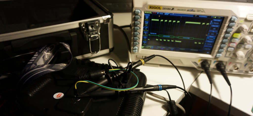
The dongle indeed is detected as a serial interface device but spits out garbage on a serial monitor. The key is here finding the correct baud rate to even start investigating data structures. Connected my trusty Rigol DS1054z and tapped the serial lines - bingo - 115200 baud with single stop bits and no parity. In the process, I have also found out that the other lines are outputting analog output, which I highly suspect, they are also inputs to the TX encoder.
Now being able to “listen to” the serial communication, I can start interpreting them. Changing parameters on the T6config software, I have screened out each feature that is configurable. Here is the byte map of the setup chunk;
55 FF START
----------------------------------------------------------------------
** STICK MODEL (0, 1, 2, 3) +
TYPE (0 ACRO, 1 HELI-120, 2 HELI-90, 3 HELI-140)
----------------------------------------------------------------------
** REVERSE (bit 0, 0, CH6, CH5, CH4, CH3, CH2, CH1)
----------------------------------------------------------------------
** ** DR ON CH 1 + DR OFF CH 1 (0-100)
** ** DR ON CH 2 + DR OFF CH 2 (0-100)
** ** DR ON CH 4 + DR OFF CH 4 (0-100)
----------------------------------------------------------------------
** SWASH AFR CH1 (-100% - 100%)
** SWASH AFR CH2 (-100% - 100%)
** SWASH AFR CH3 (-100% - 100%)
----------------------------------------------------------------------
** ** ENDPOINTSx2 CH1 (100 - 120)
** ** ENDPOINTSx2 CH2 (100 - 120)
** ** ENDPOINTSx2 CH3 (100 - 120)
** ** ENDPOINTSx2 CH4 (100 - 120)
** ** ENDPOINTSx2 CH5 (100 - 120)
** ** ENDPOINTSx2 CH6 (100 - 120)
----------------------------------------------------------------------
** ** THRO CURV MODEL NOR + THRO CURV MODEL ID  EP0 (-128 127)
** ** THRO CURV MODEL NOR + THRO CURV MODEL ID  EP1 (-128 127)
** ** THRO CURV MODEL NOR + THRO CURV MODEL ID  EP2 (-128 127)
** ** THRO CURV MODEL NOR + THRO CURV MODEL ID  EP3 (-128 127)
** ** THRO CURV MODEL NOR + THRO CURV MODEL ID  EP4 (-128 127)
----------------------------------------------------------------------
** ** PITCH CURV MODEL NOR + PITCH CURV MODEL ID  EP0 (-128 127)
** ** PITCH CURV MODEL NOR + PITCH CURV MODEL ID  EP1 (-128 127)
** ** PITCH CURV MODEL NOR + PITCH CURV MODEL ID  EP2 (-128 127)
** ** PITCH CURV MODEL NOR + PITCH CURV MODEL ID  EP3 (-128 127)
** ** PITCH CURV MODEL NOR + PITCH CURV MODEL ID  EP4 (-128 127)
----------------------------------------------------------------------
** SUBTRIM CH1 (-120 - 120)
** SUBTRIM CH2 (-120 - 120)
** SUBTRIM CH3 (-120 - 120)
** SUBTRIM CH4 (-120 - 120)
** SUBTRIM CH5 (-120 - 120)
** SUBTRIM CH6 (-120 - 120)
----------------------------------------------------------------------
** ** ** ** MIX1 (nibble SRC, DEST) + UP (-100, 100) +
DOWN (-100, 100) + SW (0 A, 1 B, 2 ON, 3,OFF)
** ** ** ** MIX2 (nibble SRC, DEST) + UP (-100, 100) +
DOWN (-100, 100) + SW (0 A, 1 B, 2 ON, 3,OFF)
** ** ** ** MIX3 (nibble SRC, DEST) + UP (-100, 100) +
DOWN (-100, 100) + SW (0 A, 1 B, 2 ON, 3,OFF)
----------------------------------------------------------------------
0* SWA (0 NULL, 1 DR, 2 ThroCut)
0* SWB (0 NULL, 1 DR, 2 ThroCut)
----------------------------------------------------------------------
0* VRA (0 NULL, 1 PitchAdj)
0* VRB (0 NULL, 1 PitchAdj)
----------------------------------------------------------------------
CHECKSUM16
It all starts with a fingerprint/sync line of 55 FF and ends with a checksum 16. Each ** represents a byte, with its explanation on the right. Multiple bytes are explained separated by + signs. After this tedious work, I plan to actually build the controller with an LCD and everything. Still, meanwhile this project is on the shelf, I thought it would be nice to share in case somebody finds it useful. This is the data received by the TX but I still need to interpret stick data that it sends, in case I need that too.
Any comments, additions or feedback? You’re welcome.
Update: To receive the data from the TX, the computer sends 55 FA 00 and the TX responds with the same exact data but with a different header of 55 FF. When sending the stick data, TX sends a much smaller packet starting with the 55 FC header.