Dumping Korg i5m PCM ROMs - part 1
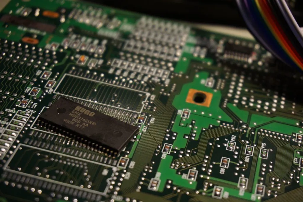
Recently I was working on fixing a korg i5m 1995 workstation -that I’ve bought as is on eBay years ago- which has a noise problem in the output. A mechanical but not random weird noise. I also have an i5s (a version with the keyboard and speakers) and I like the samples of that device, so ordered this module version for repairing. After checking voltages and power supply, I first suspected the DAC on the output stage. Easily found a replacement online, waited for it to arrive from China and replaced, with no luck, same problem. Service and user manuals are available for this model online and troubleshooting steps in the service manual turn out ok except for the checksums. But this was the same in my old working i5s, giving random checksum values each time I run the tests. After fiddling around for a while, I decided to desolder the ROM chips in order to narrow down the problem. The system has a 16 bit main bus connecting ROMs RAM and various IO and three MX23C1610MC-15 PCM mask ROMs namely PCM A, GM1 and GM2.
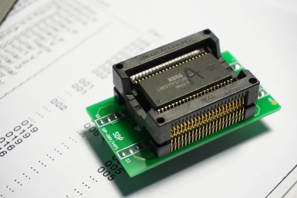
Problem still there. The sampler boots up properly, does not check if the ROMS are there on boot-up apparently. Playing the demo results in a very similar noise pattern except for no samples play this time as expected. Having removed the ROM chips I think it would be nice to have their contents on a modern file in my PC and I’ve decided to dump them out. I gave up soldering them one by one after working on it for half an hour (phew, that was close). Ordered a SOP44 adapter;
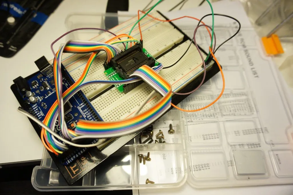
And connected the ROM to an Arduino Mega. We will put an address on the adress inputs of the chip and get the output corresponding to that memory location. I have used the chip in byte mode instead of word, getting 8 bits at a time. These chips hold 16Mbits of data each. With a quich search I come up with this little tool eeprom reader. And here is the ratsnest I’ve made (at least now I can just pop in a chip and read contents);
With the tool found on phooky’s repository, reading a single chip takes about 15 minutes and it is not easy to maintain a good connection for this long. Further, as I don’t know the contents of the chip, I wanted to make sure that I’m reading the same data each time I read it, so I need a faster method. Then I’ve written my tool based on phooky’s but this time using direct port access on Arduino. But this means we have to change the wiring to match the port layout of course. Also I’m sending raw byte data instead of human-readible hex values to minimize the data rate. With these improvements I got about 10x speedup, but I was still failing at getting consistent results. Find my optimized reader on github. Only after serious trial and error, I was able to get consistent output, which I will write about on the next part.